
CST-based airfoil aerodynamic optimization
Exploring a lower-drag airfoil under lift and geometric constraints.
00 / Context
Project overview
This case uses NACA 6416 as the baseline to show how CST parameterization, aerodynamic analysis, and automated optimization can quantify the effect of geometry changes. The objective is to minimize drag at a defined operating condition while satisfying lift, thickness, and pitching-moment requirements, supporting airfoil selection and a later three-dimensional wing study.
Under lift, thickness, and pitching-moment constraints, which geometry changes can reduce drag without creating unacceptable off-design penalties?
500
CST candidates in the design space
16
total upper and lower shape coefficients
coefficient search range
target-lift reference
01 / Resolve aerodynamic performance and geometry together
The design challenge is larger than a single low-drag point
The baseline is NACA 6416. The current configuration uses 150 points per surface, eight CST coefficients on each surface, 500 design samples, Reynolds number , and an initial evaluation angle . Mach number, pitching-moment limits, and detailed trailing-edge requirements remain project inputs and are not silently assumed.
Application
Fixed-wing aircraft / UAV airfoil selection
Study object
Two-dimensional airfoil section
Baseline
NACA 6416 geometry
Objective
Minimize at matched target
Constraints
Thickness, surface validity, trailing edge, smoothness, and
Method
CST + XFOIL screening + CFD verification
Three questions govern the study
- 01At the same lift requirement, which geometry changes genuinely reduce drag?
- 02How can the search preserve required thickness and geometric quality?
- 03Does the apparent gain remain on a refined mesh and at neighboring operating conditions?
Current study scope
The candidate geometry envelope is currently available. Baseline coefficients, matched-lift drag, pressure distributions, optimization history, and refined-mesh results require further verification; no drag-reduction claim is made at this stage.
02 / Separate geometry representation from aerodynamic gain
Start from a trusted baseline, then construct the CST model
First compute baseline lift, drag, and pitching moment using consistent freestream conditions, reference quantities, and convergence criteria; record pressure distribution, near-wall behavior, mesh resolution, turbulence, and transition treatment. Then fit the upper and lower surfaces with CST functions. Before optimization, quantify fit error around the leading edge, trailing edge, and curvature changes, and recompute the fitted baseline so representation error is never counted as optimization gain.
CST surface definition used in this study
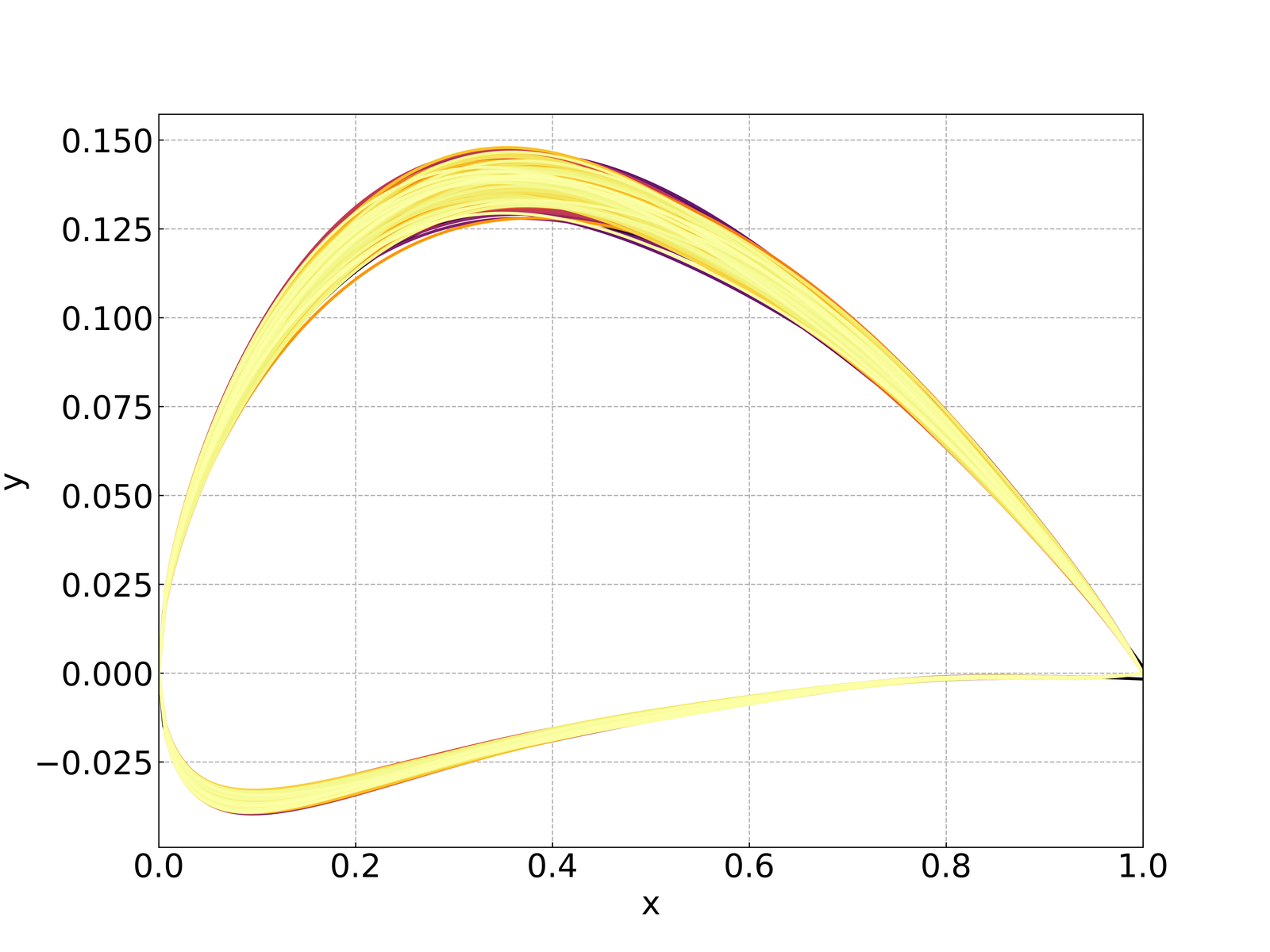
baseline / selected
- 01Quantify CST fit error against the original coordinates.
- 02Recheck baseline aerodynamics after fitting so representation error is not counted as optimization gain.
- 03Preserve thickness, trailing-edge, smoothness, and manufacturability constraints throughout the search.
Why CST is useful in an engineering workflow
Compact
Replace hundreds of coordinate ordinates with eight coefficients per surface.
Controllable
Relate coefficient changes to smooth, continuous upper- and lower-surface variations.
Automatable
Use the same variables for sampling, surrogate modeling, optimization, and design traceability.
03 / Preserve every decision in the search history
Generate, screen, solve, match lift, and rank
The automated loop generates each candidate, performs geometry checks, updates the mesh or analysis model, solves the aerodynamic condition, adjusts incidence to meet target lift, and records every design variable, objective value, and constraint state. XFOIL provides efficient two-dimensional screening; shortlisted designs then require CFD with consistent reference and convergence settings. Multi-condition projects can use weighted drag objectives while checking lift and moment constraints at every condition.
01
Generate
Create the CST candidate from its upper and lower coefficient vectors.
02
Screen
Reject invalid geometry before consuming solver time.
03
Evaluate
Obtain , , , and the target-lift incidence.
04
Decide
Rank only quality-admitted candidates and retain full provenance.
Analysis data retained for each design
The workflow uses Latin-hypercube sampling for the upper and lower CST coefficients, writes each candidate as an airfoil coordinate file, runs batch XFOIL at , and prepares , , , , , and for tabular export. Kriging and genetic-algorithm routes support subsequent optimization studies; final NACA 6416 conclusions require the complete verification sequence below.
objective / constraints
–
04 / Define the engineering verification boundary
Every maturity gap becomes an explicit delivery gate
The parameterized workflow provides the design foundation, while a commercial design decision also requires strict objective matching, constraint enforcement, solver quality control, and independent verification. The table below defines the current scope and the acceptance requirement for each workstream.
| Workstream | Current scope | Verification requirement |
|---|---|---|
| Geometry | NACA 6416 fitted with CST; 500 perturbed candidates available | Fit tolerance, minimum thickness, trailing edge, curvature, and self-intersection checks pass |
| Operating point | XFOIL batch evaluation at and | Mach number, transition model, roughness assumption, and matched target are defined |
| Objective | and retained; lift reference | The agreed drag objective is evaluated at matched lift across all candidates |
| Optimization | Kriging and GA routes included in the method | Selected result is reproducible from a versioned configuration and complete history |
| Verification | Aerodynamic comparison remains under review | Baseline and selected designs pass convergence, mesh, and neighboring-condition CFD checks |
Decision boundary
A candidate becomes a recommended airfoil only after it passes every release gate. Before that point it is a screening result, not a validated design recommendation.
05 / Test whether the gain is larger than numerical variation
The selected section must survive refined-mesh and neighboring-condition checks
The baseline and shortlisted airfoils should be recomputed with identical, refined settings. The comparison must cover the target lift and nearby operating range, then test sensitivity to Reynolds number, Mach number, transition treatment, and mesh resolution. A two-dimensional result supports section selection; it does not establish whole-aircraft range or endurance.
/
mesh study
Minimum acceptance checks
- 01Force and moment histories meet declared convergence criteria, with residual behavior documented.
- 02Matched-lift improvement is larger than the estimated numerical uncertainty.
- 03Thickness, trailing-edge, curvature, and pitching-moment limits remain feasible.
- 04The selected airfoil shows no unacceptable loss across the agreed neighboring operating range.
Result interpretation
Do not publish ‘lower drag’, ‘delayed separation’, or a percentage improvement until is compared at matched and the result passes convergence, mesh, and neighboring-condition checks.
06 / Use a consistent evaluation framework
Baseline and selected designs will be compared on common terms
The baseline and selected airfoils are compared at the same Reynolds number, Mach number, and target lift coefficient. Performance values are marked for verification until the complete calculation and review sequence is finished.
| Metric | Baseline | Selected design |
|---|---|---|
| Lift coefficient | To be verified | To be verified |
| Drag coefficient | To be verified | To be verified |
| Lift-to-drag ratio | To be verified | To be verified |
| Angle at target lift | To be verified | To be verified |
| Pitching-moment coefficient | To be verified | To be verified |
| Maximum relative thickness | To be verified | To be verified |
| Geometry and moment constraints | To be verified | To be verified |
How the result will be read
Performance
Compare only at matched ; report both absolute change and percentage change.
Feasibility
Treat thickness and as design requirements, not secondary observations.
Robustness
Report where the gain persists, disappears, or reverses across neighboring conditions.
Result interpretation
Pressure distribution and near-wall flow are used to identify the physical mechanism, while neighboring conditions define the benefit range and associated trade-offs.
07 / What this workflow is designed to deliver
A decision-ready airfoil evidence package
01
Quantified trade-offs
Expose the relationship among drag, lift, thickness, pitching moment, and operating range.
02
Traceable selection
Retain coordinates, CST coefficients, objective values, constraints, and solver evidence for every accepted candidate.
03
A disciplined handoff
Advance only credible sections to three-dimensional wing analysis, trim studies, and experimental validation.
Project deliverables
- 01Baseline and selected airfoil coordinates with CST coefficients
- 02Design condition, objective, and constraint definition
- 03CFD setup, mesh, convergence, and verification records
- 04Optimization history and candidate comparison
- 05Aerodynamic curves, flow interpretation, and final review report
- 06Recommendations for three-dimensional design and experimental validation
Recommended next phase
01
Freeze the brief
Confirm mission point, , , target , thickness, , and manufacturing limits.
02
Complete the evidence
Run the baseline, qualify the design space, optimize, and independently verify shortlisted sections.
03
Escalate deliberately
Move the selected section into three-dimensional wing, trim, propulsion-coupling, and test studies.
Study basis
The study configuration is based on the NACA 6416 airfoil design workflow. CST method context follows the pyGeo CST airfoil tutorial; performance conclusions are released after the defined verification requirements are satisfied. pyGeo CST tutorial
Could your airfoil have more performance potential?
Turn geometry freedom into a defensible aerodynamic decision.
Share the airfoil coordinates, target speed or Reynolds number, lift requirement, and geometric limits. We can define the analysis scope and optimization objective around them.